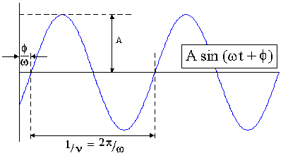

In wave mechanics, the phase is defined as the difference between identical reference points on two waves. Consider for example, the figure below. We can define a reference point as the x or "t" value wherein y = 0 and dy/dx > 0. If one were to then superimpose a 2nd wave, initiated at the axis origin, then the phase of the displayed sinusoidal wave would be f and the phase angle would be f/w.

In electrophoretic light scattering, or more specifically laser Doppler electrophoresis, a phase plot shows the difference in phase between the measured heterodyned "beat" signal and a superimposed reference signal of known frequency.
Laser Doppler electrophoresis measures small frequency shifts in the scattered light that arise due to the movement of particles in an applied electric field. The frequency shift is measured using a method called heterodyning, wherein a fraction of the incident light source is added to the scattered signal to produce a beat signal, the frequency of which can be measured with an intensity detector (APD). The frequency of the beat signal is a function of the absolute value of the frequency shift of the scattered light and hence the mobility of the particle. To calculate the Doppler shift of the scattered light, and hence the electrophoretic mobility of the charged particles, one need only measure the beat frequency of the heterodyned signal.
While the heterodyning technique is straightforward in theory, in practice, numerous waveforms must be collected at the APD in order to ensure an unambiguous measure of the beat frequency. To further convolute the measurement, the beat frequency will only give the absolute value of the frequency shift between the reference and the scattered beams. In order to determine the sign of the frequency shift, and hence the direction of particle motion, a reference frequency must be superimposed onto the waveform of the beat signal. In the Zetasizer Nano system, this reference frequency is produced by modulating the incident light signal added to the scattered signal, using an oscillating mirror. The result is a beating wave form, the frequency of which oscillates with time – further increasing the number of waveforms that must be collected during the course of the measurement. The approach in fact, proves to be particularly problematic when working with low mobility samples in high conductivity solutions. Under these conditions, the effect of the applied field can be weak, leading to low beat frequencies and very long measurement times.
Fortunately, a solution to the above dilemma was presented with the development of phase analysis light scattering (PALS). With the PALS method of signal processing, it is the phase difference between the beat signal and reference of known frequency that is calculated. Since information regarding this phase difference is contained within each point of the time trace for the beat waveform, the same amount of information can be collected with only a fraction of the waveform. By definition, "phase" is equivalent to the product of the frequency and the time, and as such, the frequency shift (or difference) can be directly calculated from the measured phase difference.
As defined earlier, a phase plot shows the difference in phase between the measured heterodyned beat signal and the superimposed reference signal as a function of time. The figure below shows a typical phase plot of good quality, obtained from an electrophoretic light scattering measurement using the General Purpose protocol in the Zetasizer Nano software. As noted in this figure, the phase plot shows well defined, alternating slopes of the phase difference with time, during the fast field reversal (FFR) portion of the measurement (up to 1.2 seconds). In the M3 Technique, the slopes in the FFR portion are averaged to determine the mean phase difference, and subsequent average electrophoretic mobility and zeta potential. As also evident in this figure, the slopes of the phase difference during the slow field reversal (SFR) portion of the measurement, which is used in the M3 Technique to determine the distribution of zeta potentials, are also smooth and well defined.

For additional questions or information regarding Malvern Instruments complete line of particle and materials characterization products, visit us at www.malvern.com.
